
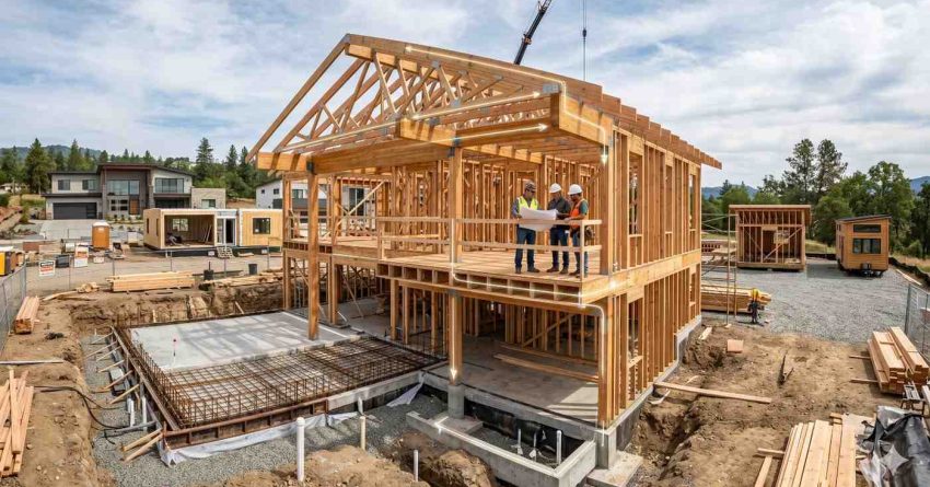
Foundations, framing, and structural systems are the three interconnected layers that determine whether your new home stands safely for decades or develops expensive problems in its first few years. Every load your home experiences — gravity, wind, snow, and seismic force — travels through these systems from roof to ground.
Choosing the wrong foundation type, framing method, or structural connection for your climate and soil creates defects that are invisible at completion and catastrophically costly after the fact.
This guide covers foundation types and selection, framing methods from stick frame to ICF, engineered lumber, structural engineering fundamentals, climate-specific code requirements, foundation problems and warning signs, and inspection priorities at every critical build phase.
What Are Foundations, Framing & Structural Systems?
Foundations, framing, and structural systems are not three separate topics — they are a single integrated engineering system that works as a chain. Every link in that chain must be correctly designed, correctly built, and correctly connected for the system to perform as intended under real-world conditions.
The Three Interconnected Layers of Every Home
The foundation is the below-grade or at-grade structural element that transfers all building loads — the weight of the structure, its contents, wind pressure, and seismic forces — safely into the bearing soil beneath it. A foundation must not settle unevenly, resist moisture intrusion, and remain stable across decades of soil movement, temperature cycling, and frost pressure.
The framing system is the structural skeleton of the building above the foundation — walls, floors, and roof — assembled from dimensional lumber, engineered wood products, structural panels, or steel. Framing carries all vertical loads downward to the foundation and resists all lateral loads (wind and earthquake) through braced panels, shear walls, and rigid connections.
Structural systems encompass the engineering principles, connection hardware, and engineered components — beams, columns, trusses, hold-downs, anchor bolts, hurricane clips — that integrate foundation and framing into a complete load-resisting structure. Understanding structural systems means understanding how loads are transferred, where connections are required, and what happens when any element is undersized or missing.
Why These Decisions Cannot Be Undone
Unlike countertop materials or paint colors, structural and foundation decisions are locked in at the earliest phases of construction. Foundation type is determined during site analysis before design is finalized. Framing method is committed before permits are submitted. Structural engineering calculations set header sizes, shear wall locations, and connection hardware — all embedded in the structure before insulation, drywall, and finishes conceal them.
Changing a foundation type after excavation begins or relocating a structural wall after framing is complete carries costs that can equal or exceed the value of all the work done to that point. Getting these decisions right — with the right professional input and the right foundational knowledge — is one of the highest-value investments you can make before a project begins.
Foundation Types: Your First and Most Critical Decision
Every residential structure begins with a foundation, and every foundation type accomplishes the same goals — supporting the home’s weight, resisting lateral forces, and separating the living space from the earth — through a different structural and geometric approach. Understanding the four primary foundation types at the orientation level is the prerequisite for every site selection, design, and cost conversation that follows.
Slab-on-Grade Foundations
The slab-on-grade foundation is a single continuous concrete pad poured directly on compacted soil or a prepared aggregate base. It is the dominant foundation choice across the South, Southwest, and coastal West, where frost depth is minimal, termite pressure is high, and simple slab construction is both structurally appropriate and economically rational. A properly reinforced slab — with a perimeter thickening at the footing, a vapor barrier beneath the concrete, and either conventional rebar or post-tension cables in expansive soil regions — provides decades of reliable structural performance with minimal maintenance.
Slabs are typically the fastest and least expensive foundation option because they combine the floor system and foundation into a single pour. The primary trade-off is that all plumbing beneath the slab is buried in or under the concrete, making future repairs significantly more expensive than in crawlspace or basement configurations. Our guide to slab-on-grade foundation design covers reinforcement schedules, vapor barrier requirements, and post-tensioned slab configurations for expansive soil conditions — all the information your engineer and builder need before the first concrete truck arrives.
The two primary slab configurations — monolithic vs. stem wall slab design — differ significantly in how edge support, frost protection, and point load transfer are handled, and your structural engineer and local frost-depth map will determine which is appropriate for your specific site.
Crawlspace Foundations
A crawlspace foundation raises the home 18 to 48 inches above grade on continuous perimeter walls or piers, creating an accessible but non-habitable space beneath the floor structure. This configuration allows plumbing, HVAC ductwork, and electrical runs to travel beneath the floor deck where they remain visible, accessible, and serviceable without cutting through concrete — a significant long-term maintenance advantage.
Crawlspace foundations are common in the Southeast, Pacific Northwest, and mid-Atlantic, where MEP accessibility, moisture management needs, and moderate frost exposure all factor into the selection. Our guide to crawlspace foundation systems explains the structural configuration, minimum height requirements, and typical cost range so you can evaluate whether a crawlspace is the right foundation for your climate zone and lot conditions.
The critical variable in any crawlspace is moisture management — either through traditional vented vs. encapsulated crawlspace design approaches that produce dramatically different long-term moisture, energy, and structural performance outcomes, particularly in high-humidity regions where unconditioned vented crawlspaces can produce chronic moisture problems within the first few years of occupancy.
Basement Foundations (Full, Walkout, and Daylight)
A basement foundation extends the building footprint 8 to 10 feet below grade, creating fully usable below-grade space that can be finished into habitable rooms, mechanical space, storage, or recreation areas. Basements are the dominant foundation type in the Midwest, Northeast, and Great Plains, where frost depths ranging from 36 to 60 inches make deep footing requirements economically rational to extend into a full below-grade story.
The three basement configurations — full basement (entirely below grade), walkout basement (one or more walls above grade with direct exterior access at grade level), and daylight basement (partial exposure of one wall above grade, allowing windows) — each create different structural configurations, waterproofing requirements, and egress opportunities. A full basement adds the most below-grade livable area; a walkout offers the most natural light and the most direct exterior access; a daylight configuration suits hillside lots where grade naturally exposes part of the foundation wall.
Pier and Beam and Specialized Foundations
Pier and beam construction elevates the structure on vertical piers embedded in the soil, with horizontal beams spanning between piers to carry the floor system. This approach is used in coastal flood zones (where elevation above base flood elevation is required), rural builds on uneven terrain, and regions where expansive or poorly bearing soils make a continuous foundation impractical without extreme reinforcement.
For sites with very poor bearing soils or highly variable surface conditions, helical pile foundations provide an engineered alternative that bypasses problematic near-surface soils entirely by anchoring to deeper stable strata, making them increasingly common for ADU foundations, soft-soil coastal sites, and urban infill projects. In cold climates where an unheated structure requires code-compliant frost protection without the cost of a full-depth foundation, a frost-protected shallow foundation achieves performance comparable to a deep conventional footing at a fraction of the excavation cost by using perimeter insulation to prevent frost penetration beneath the footing.
For the complete side-by-side evaluation of all four major foundation types — including structural performance, drainage requirements, regional cost ranges, and climate suitability — our guide to foundation types compared covers slab, crawlspace, basement, and pier-and-beam systems in full detail so you can arrive at every design conversation with a clear understanding of the tradeoffs involved.
How to Choose the Right Foundation for Your Site
The foundation type decision is not primarily a preference — it is an engineering judgment driven by your site’s specific physical conditions. Three variables dominate the analysis on every new build: climate zone, soil type, and lot topography.
Climate Zone — The Primary Structural Driver
Climate determines frost depth — the depth to which soil freezes in winter — which in turn sets the minimum depth for all footings and foundation walls under the International Residential Code. In IECC Climate Zone 7 (northern Minnesota, Montana, North Dakota), frost depths regularly exceed 60 to 72 inches, making uninsulated slab-on-grade essentially non-compliant without significant frost protection measures. In Climate Zone 2 (Florida, coastal Texas, Hawaii), frost is absent, making slab-on-grade the structurally and economically optimal choice for most sites.
Climate also shapes moisture management requirements. High-rainfall climates like the Pacific Northwest and Southeast put foundations in regular contact with elevated soil moisture, favoring crawlspace or basement designs with robust waterproofing and drainage systems. Arid climates like the Southwest introduce expansive clay soil as a more significant concern than moisture infiltration, driving the use of post-tensioned slabs or reinforced foundations designed for soil movement rather than hydrostatic pressure.
Our guide to foundation choice by climate zone maps every IECC climate zone to the most structurally sound and cost-effective foundation type, from frost-depth minimums in northern Zone 7 builds to termite pressure and moisture exposure management in southern Zone 1 and 2 regions.
Soil Type and Geotechnical Testing
Soil bearing capacity — measured in pounds per square foot — determines how much load the soil can support and what foundation geometry is needed to distribute building loads without exceeding that capacity. Sandy, well-draining soils with high bearing capacity can support relatively simple foundation designs. Highly expansive clay soils — common in Texas, Colorado, and parts of the Carolinas and California — exert significant upward and lateral pressure on foundations as they swell and shrink with seasonal moisture content changes, requiring post-tensioned slabs, deepened footings, or pier systems that extend below the active soil zone.
Geotechnical testing — a soil investigation conducted by a licensed geotechnical engineer — is not universally required by code for single-family residential construction, but it is always advisable on sites with unknown soil conditions, visible evidence of fill or disturbed ground, proximity to water features, or a history of foundation problems in nearby structures. Our guide to foundation selection by soil type explains how expansive clay, sandy loam, bedrock, and engineered fill each dictate a structurally different approach and what geotechnical testing your engineer needs before a foundation type can be responsibly specified.
Lot Slope and Topography
Sloped lots introduce structural complexity that flat-lot foundations do not face. A grade change of more than 3 feet across the building footprint typically requires either stepped footings that follow the natural grade change, a retaining wall at the downhill side to create a level pad, or a full basement/walkout configuration that uses the hillside as the structural backdrop for the below-grade wall.
Our guide to foundation design for sloped lots covers stepped footing requirements, walkout and daylight basement configurations, retaining wall integration at the foundation level, and the structural connection details that keep hillside foundations performing correctly through decades of soil movement and seasonal expansion and contraction cycles.
What a Foundation Costs — and What Drives the Price
Foundation work typically represents 10 to 15 percent of a new home’s total construction budget — but the range within that percentage is substantial, shaped by foundation type, site conditions, regional labor markets, and material pricing that has seen significant volatility since 2020.
Cost Range by Foundation Type
Nationally, slab-on-grade foundations are the least expensive option in most markets, averaging $6 to $14 per square foot depending on reinforcement level, concrete thickness, and whether post-tensioning is required. Crawlspace foundations add the cost of perimeter block or poured concrete walls, floor joists, and sheathing — typically $8,000 to $20,000 more than a comparable slab — but they reduce MEP installation complexity and improve long-term serviceability. Full basement foundations carry the highest upfront cost due to excavation volume, concrete wall height, waterproofing requirements, and drainage system installation, but they also deliver the highest ratio of livable square footage per construction dollar when the space is fully finished.
What Drives Costs Above the Average
Beyond foundation type, the variables that most significantly escalate foundation costs include: rock that requires blasting or hydraulic breaking before excavation can proceed; high water table conditions that require permanent dewatering systems or upgraded waterproofing membranes; highly expansive soils requiring post-tensioning or additional reinforcement; regional concrete price volatility (which has increased 15 to 30 percent in most US markets over the past four years); and contractor availability in markets where skilled concrete and foundation crews are in short supply.
Our detailed foundation cost breakdown provides per-square-foot pricing across all major foundation types, regional cost variation data from multiple US markets, and the site conditions — including rock, high water table, expansive soil, and steep slope — that most commonly push foundation budgets above the initial contractor estimate.
Foundation Waterproofing, Drainage & Protective Systems
A structurally sound foundation that admits water or moisture will develop problems that are expensive to remediate and damaging to the structural framing above it. Waterproofing, drainage, and protective treatment systems are engineering components, not optional upgrades — they determine whether your foundation performs as designed across a 50-to-100-year service life.
Waterproofing vs. Damp-Proofing
Damp-proofing is the minimum treatment applied to exterior foundation walls to resist moisture vapor transmission through concrete or masonry. It consists of a brush or spray-applied bituminous coating and provides only limited protection against liquid water under pressure. Full waterproofing is a more robust system — typically a sheet-applied or fluid-applied membrane designed to resist hydrostatic pressure from groundwater that accumulates against the foundation.
The distinction matters critically in practice: damp-proofing is adequate in well-drained, dry-climate conditions where liquid water simply doesn’t accumulate against the foundation; full waterproofing is the appropriate standard in any location with heavy annual rainfall, elevated water table, clay soils that retain moisture, or a basement configuration where interior-grade living space is at risk. Our guide to foundation waterproofing systems explains the technical difference between both approaches, which materials perform best by soil moisture condition, and when local building code mandates full waterproofing rather than the minimum damp-proofing treatment.
Foundation Drainage Systems and Footing Drains
Even the most effective waterproofing membrane performs better when groundwater pressure is relieved by an active drainage system rather than allowed to accumulate against the wall. Footing drains — perforated pipe installed at the base of the foundation footing, surrounded by drainage aggregate and filter fabric — collect groundwater before it can build hydrostatic pressure against the foundation wall and route it away from the building to daylight or a sump basin.
Proper surface grading — a minimum 6-inch drop in the first 10 feet from the foundation — is the first and most cost-effective drainage measure, directing surface water away from the foundation before it can infiltrate the soil adjacent to the wall. Our guide to foundation drainage design covers exterior footing drain installation specifications, interior drain tile options for basement configurations, sump pump sizing and redundancy, and the grading and swale design that protects foundations in both new construction and remediation scenarios.
Radon, Termites, Vapor Barriers & Foundation Insulation
Four protective measures deserve priority attention at the foundation stage because they are dramatically less expensive to implement during construction than after the foundation is complete.
Radon — a naturally occurring radioactive gas that enters homes from underlying soil — is the second-leading cause of lung cancer in the United States. Passive sub-slab depressurization systems cost under $500 to rough in during slab construction and under $1,500 to activate with a fan if post-occupancy radon testing returns results above the EPA’s 4 pCi/L action level. Our guide to radon mitigation in new construction explains which EPA radon zones carry elevated risk, how the passive system is roughed in before the slab pour, and how to verify system performance through post-construction testing before the warranty period expires.
Termite pre-treatment, applied to the soil or structural lumber before the slab is poured, creates a chemical barrier protecting against subterranean termite infestation — the leading cause of structural wood damage in US residential buildings. Pre-treatment is mandatory by code in many southern and coastal states and strongly advisable anywhere with documented termite pressure.
Vapor barriers under slabs reduce moisture vapor transmission from the soil into the slab and living space, preventing the concrete from acting as a wick that delivers soil moisture into the home. Foundation insulation — applied to exterior or interior foundation walls in cold climates — reduces heat loss through the below-grade building envelope and eliminates the thermal bridging at the footing-to-wall connection that can account for a significant share of total building heat loss in conventionally built northern-climate homes.
Framing Systems: The Structural Skeleton of Your Home
Once the foundation is cured and ready for load, framing begins — the process of erecting the structural skeleton that defines every wall, floor, and roof plane of the finished building. Multiple framing systems are in current residential use across the United States, each carrying distinct structural performance characteristics, energy performance implications, cost profiles, and learning curves for the labor force installing them.
Platform (Stick) Framing — The Dominant American Method
Platform framing using dimensional lumber (2×4 or 2×6 studs at regular on-center spacing, with engineered joists and prefabricated trusses at floor and roof levels) accounts for more than 90 percent of new single-family home construction in the United States. In this system, each floor is framed and decked before the next story’s walls are erected — creating a stable working platform at each level that gives the method its name.
The dominance of stick framing reflects its combination of widely available materials, universally familiar labor, design flexibility that accommodates complex geometries, and complete code compliance in all 50 states under the International Residential Code. For most builds, stick framing is the lowest-risk, most cost-predictable foundation choice. Our guide to stick framing for new homes walks through platform vs. balloon framing configurations, stud spacing options at 16 and 24 inches on center, header sizing above openings, and why the shift from 2×4 to 2×6 framing at 24-inch spacing significantly improves thermal performance without compromising structural integrity.
A less-discussed but structurally important distinction within conventional stick framing is platform framing vs. balloon framing — configurations that differ in how studs span across floor levels, how fire blocking is integrated between stories, and how each system behaves under lateral load in two-story construction — a distinction that becomes relevant in tall wall designs, open gable conditions, and seismic zone framing plans.
SIPs (Structural Insulated Panels)
Structural insulated panels are factory-manufactured composite panels consisting of a rigid foam insulation core — typically expanded polystyrene (EPS) — bonded between two structural skins of oriented strand board. SIPs function simultaneously as structure, insulation, and air barrier, replacing the separate functions of studs, batt insulation, and housewrap with a single precision-engineered component that eliminates the thermal bridging inherent in conventionally framed stud walls.
Homes built with SIPs consistently achieve tighter air infiltration rates, higher effective wall R-values, and faster framing schedules than conventionally framed buildings — with air infiltration test results routinely 30 to 50 percent better than comparable stick-framed structures. The tradeoffs are a more demanding design coordination process, stricter field installation requirements for panel connection details, and less flexibility for post-construction modifications to wall routing. Our guide to SIP panel construction covers panel thickness and R-value performance by climate zone, SIP-to-foundation connection detailing, a realistic cost comparison with stick framing, and the design and logistics considerations that make SIPs the right choice for performance-focused and fast-tracked builds.
ICF Wall Construction
Insulated concrete form (ICF) walls consist of interlocking rigid foam blocks that function as both the stay-in-place formwork for a poured concrete wall and the permanent thermal insulation on both faces of the wall. Once the concrete is placed and cured, an ICF wall delivers the structural strength and thermal mass of concrete with continuous foam insulation that eliminates thermal bridging at every wall stud location — a performance combination that conventional framing methods cannot replicate.
ICF construction is particularly compelling in extreme climates — both hot-dry desert environments where thermal mass moderates peak cooling loads, and cold climates where winter heating efficiency is the primary design driver. ICF walls also deliver superior resistance to wind pressure, fire, moisture intrusion, pest damage, and sound transmission compared to wood-frame walls of comparable thickness. The cost premium over stick framing — typically 3 to 8 percent of total construction cost when fully accounted — is offset over time by reduced heating and cooling energy costs that in high-performance climate scenarios can approach payback within 10 to 15 years.
Timber Frame and Post and Beam
Timber frame and post-and-beam construction use large-section structural timbers — typically 6×6, 8×8, or larger — as the primary structural members, creating wide, open bays between columns that are enclosed with infill panels (often SIPs for insulation value) rather than continuous stud walls. The visual expression of heavy timber joinery and exposed structural members within the finished space is a defining aesthetic of this construction type.
The structural performance of timber frame construction is well-suited to long-span, open-plan designs: large timber members resist lateral forces without the shear wall requirements of dimensional lumber framing, and properly executed timber connections can accommodate spans that would require multiple interior bearing walls in a conventionally framed building. The significant cost premium over stick framing reflects the specialty labor required for precision timber joinery, the material cost of large-section timbers in non-commodity species, and the design complexity of integrating insulation and air sealing into a structural system that requires custom panel infill solutions.
For builders seeking the energy familiarity of dimensional lumber with measurably better thermal performance than standard 2×4 construction delivers, our guide to advanced framing techniques details the Optimum Value Engineering approach — including 24-inch on-center stud spacing, single top plates, and engineered two-stud corners — that reduces lumber volume by 15 to 20 percent while increasing the insulated cavity area available for continuous insulation in any climate zone.
Engineered Lumber, Floor Systems & Roof Structures
Modern residential construction depends heavily on engineered wood products that outperform dimensional lumber in span capability, dimensional stability, and structural predictability — enabling builders to achieve longer clear spans, flatter floors, and more efficient framing designs than traditional sawn lumber permits.
LVL, PSL, and Glulam Beams
Laminated Veneer Lumber (LVL), Parallel Strand Lumber (PSL), and glued laminated timber (glulam) are the three primary engineered beam products used in residential construction for long-span header applications: garage door openings, floor transfer beams, ridge beams in vaulted ceiling configurations, and large window or door headers in open-plan facades.
LVL is manufactured by bonding thin wood veneers with waterproof adhesive under heat and pressure, producing a beam with significantly higher bending strength than dimensional lumber of the same cross-section. PSL bonds parallel wood fiber strands for excellent long-span performance and consistent strength across large cross-sections. Glulam combines dimensional lumber laminations for applications where large cross-sections, long spans, or curved profiles are required architecturally or structurally. Our guide to engineered lumber for residential builds compares all three products across cost, application, span table requirements, moisture sensitivity, and the structural design scenarios where each product delivers the highest performance-to-cost ratio.
I-Joists vs. Dimensional Lumber Floor Joists
Engineered I-joists have replaced dimensional sawn lumber as the standard floor framing component in new residential construction across most US markets. Their I-shaped cross-section — top and bottom flanges of structural lumber bonded to a structural OSB or plywood web — allows them to span greater distances than dimensional joists of equivalent depth, resist the warping and crown that cause uneven floors in older framed buildings, and accommodate larger MEP penetrations through factory-punched knockout holes that eliminate field notching and its associated structural compromise.
The structural efficiency of I-joists means fewer material resources are consumed to achieve a given structural performance level, and the factory quality control produces more consistent, predictable performance than graded dimensional lumber cut from variable old-growth and plantation timber. The primary consideration in I-joist specification is proper bearing condition: I-joists require adequate bearing at each end, proper blocking at support points, and squash blocks at any concentrated load transfer location — details that must be confirmed in the framing plan before materials are ordered.
Roof Trusses vs. Stick-Framed Roof
Prefabricated roof trusses — engineered in a factory setting to the exact snow, wind, and dead load conditions of the specific building — account for the majority of residential roofs in the United States. Factory engineering to the actual loading conditions of each project produces a structurally optimized result with verified load capacity at every member and connection, delivered as a coordinated package that can be craned into position and fastened in a single day for a typical single-family home.
Our comparison of roof truss vs. site-framed roof breaks down when prefabricated trusses win on cost, speed, and structural precision, and when hand-framing wins for vaulted ceilings, finished attic rooms, complex multi-plane roof geometries, or sites where truss delivery logistics are impractical — along with what changes in the permit drawings and structural engineering documentation when each approach is selected.
Wall and roof sheathing selection — the structural panels that connect and stiffen framing members while providing a nail base for exterior cladding and roofing — is one of the most frequently debated material decisions in residential framing. Our comparison of OSB vs plywood wall sheathing covers structural performance under racking load, moisture resistance and edge swelling behavior, regional cost differences, and when local building code or a structural engineer’s specification requires one material over the other in high-wind or seismic applications.
Structural Engineering Principles Every Builder Should Understand
The majority of homeowners engage structural engineers only when a lender or permit office requires it. But understanding the foundational principles of residential structural engineering helps you ask better questions, identify potential errors before they are built, and make more informed decisions across the entire design process.
Dead Load, Live Load, Snow Load & Wind Load
Every structural element in your home is sized to safely carry a combination of forces:
Dead load is the permanent, unchanging weight of the building’s own materials — framing, sheathing, roofing, drywall, flooring finishes, and fixed mechanical systems. It’s constant and highly predictable.
Live load is the variable weight imposed by occupants, furniture, and stored items. Building codes specify minimum live load requirements by use: bedroom and living area floors are designed for 40 pounds per square foot (psf), decks for 40 to 60 psf, and storage areas for 100 psf or more depending on application.
Snow load varies dramatically by geography — from near-zero in southern coastal states to 80 to 150 psf or more at high-elevation mountain sites — and is the primary driver of roof structure design, truss sizing, and eave design in cold climate states. Wind load is the lateral and uplift force exerted on the building envelope and is the defining structural design parameter in hurricane-prone coastal markets and high-wind inland areas.
Understanding how these load categories are combined in structural analysis — including the concurrent load combinations that govern critical structural element sizing — is explained in plain language in our guide to structural load calculations, which translates engineering principles into the practical context relevant to homeowners, landlords, and property managers.
The Continuous Load Path
The continuous load path is the engineering principle that every structural element must be physically connected to the element below it, creating an unbroken chain of force transfer from the roof structure to the foundation. In a fully designed continuous load path: roofing is fastened to sheathing, sheathing is nailed to trusses or rafters, trusses are connected to the top plate with hurricane clips, top plates are fastened to studs, studs are connected to bottom plates, bottom plates are anchor-bolted to the foundation wall, and the foundation wall is structurally tied to the footing below.
Any break in this chain — a missing connector, a fastener of incorrect type or quantity, or a framing configuration that bypasses a specified connection — creates a structural weak point that may perform adequately under normal service conditions and fail catastrophically under the first extreme wind or seismic event. Modern building codes in high-wind and seismic zones specify every connection in this chain in detail and require inspection at each phase.
Shear Walls, Headers & Lateral Resistance
Shear walls are structural wall segments specifically engineered to resist the horizontal forces imposed on buildings by wind and earthquakes. Unlike ordinary stud walls, which resist only vertical loads, shear walls are designed with specific structural panel nailing patterns, full-height blocking, and anchorage at top and bottom — details that must be built exactly as specified to achieve the design lateral resistance.
Headers — horizontal structural members above window and door openings — carry the vertical load from the structure above the opening and transfer it to the jack and king studs on each side of the opening. Undersized headers are among the most frequently identified framing defects in both new construction inspections and existing home structural assessments.
Our guide to shear wall design and placement explains how shear walls are identified in structural plans, where they must be located relative to building geometry and loading centers, what nailing patterns and hold-down hardware connect them to the foundation, and why their position cannot be modified during framing without a structural engineering review — a re-analysis that is legally required in most jurisdictions and practically essential in any high-wind or seismic zone.
When to Hire a Structural Engineer
Residential building codes do not require a licensed structural engineer (SE) for standard single-family construction that follows the International Residential Code’s prescriptive provisions. However, a structural engineer is either required or strongly advisable when: the design significantly deviates from prescriptive code defaults through large open spans, unusual concentrated loads, or complex roof geometry; the site is located in a high-seismic or high-wind zone with engineered design requirements; geotechnical conditions require a custom foundation design; or the owner is modifying load-bearing conditions in an existing structure.
Our guide to working with a structural engineer explains precisely when an SE is required versus recommended, how to verify credentials and experience in residential construction, what stamped structural plans cost across different project scales, and how their engineering documentation integrates with your architect’s drawings and your builder’s construction permit package from design phase through inspections.
Climate-Specific Structural Requirements
Building codes are not uniform across the United States. They begin with the International Residential Code as a national base standard, but every state and many local jurisdictions amend that base to address the specific structural hazards of their region. Understanding how your climate zone shapes the structural requirements of your build is essential before design documentation begins.
Hurricane Zones — Strapping, Clips & the Continuous Load Path
In Florida, coastal Texas, the Gulf Coast, and much of the Southeast coast, structural code requirements for wind resistance are substantially more demanding than those applying to inland markets. Florida’s Building Code High-Velocity Hurricane Zone provisions, for example, require not just hurricane straps at rafter-to-top-plate connections, but a fully documented continuous load path from the roofing fasteners to the foundation, verified by inspection at each construction phase.
The metal connector hardware that achieves this continuous load path — including hurricane clips, H-straps, double hurricane straps, and hold-down anchors at shear wall ends — is not optional in wind exposure categories B, C, and D: it is a code mandate whose absence is one of the most commonly cited defects in both construction inspections and post-storm forensic assessments. Our guide to hurricane strapping and clip requirements details the specific metal connectors required at every framing junction, how they establish the continuous load path that keeps homes standing in 150-mph wind events, and which products meet current requirements under the Florida Building Code, the ASCE 7 wind speed maps, and the International Residential Code high-wind amendment provisions.
Earthquake Zones — Lateral Bracing & Seismic Design Categories
California, the Pacific Northwest, Alaska, parts of the Intermountain West, and several areas of the New Madrid Seismic Zone in the Central US sit in regions where building code requires specific engineering measures that the base IRC prescriptive provisions do not fully address. Seismic Design Categories (SDCs A through F) are assigned to each building site based on mapped ground motion and local soil amplification factors, and they determine the scope of seismic engineering required for that specific project.
Even in moderate SDC B and C regions — which cover substantial portions of the South, Midwest, and East Coast — code-compliant anchor bolt sizing, spacing, and embedment, shear wall placement and nailing, and hold-down anchorage at shear wall ends are all required and must be included in permit drawings. In SDC D, E, and F regions (most of coastal California, the Pacific Northwest coast, and interior Alaska), prescriptive IRC provisions are insufficient and structural engineering is effectively required to produce a code-compliant design.
Our guide to seismic bracing for new residential construction explains Seismic Design Categories A through F, how they drive anchor bolt spacing, shear wall length requirements, and hold-down hardware selection, and the specific engineering elements that owners in high-seismic zones should proactively request from their builder’s structural engineer before framing documents are submitted for permit.
Snow Load, Wildfire & Termite Considerations
In mountain and northern states, roof structures must be engineered for the ground snow loads applicable to each specific site — which vary dramatically with elevation, aspect, and local topography, sometimes exceeding 150 psf at high-altitude ridge locations even in states where valley locations carry only 30 psf loads. Roof pitch, truss geometry, eave width, and ridge beam sizing must all be calculated for the actual mapped snow load at the building’s elevation and exposure category, not an averaged regional value.
In Wildfire Urban Interface (WUI) zones — covering significant portions of California, Colorado, Oregon, Washington, and other western states — fire-resistant roofing materials, ember-resistant vent assemblies, and specific exterior wall assembly requirements interact with framing decisions in ways that must be coordinated early in the design process. And in the Southeast, Gulf Coast, and lower Pacific Coast, termite-resistant framing strategies — including borate lumber treatment, physical termite barriers at the foundation-to-framing interface, and soil pre-treatment — are structural and code considerations, not just pest management choices.
Foundation Problems: What to Recognize and What to Do
Even properly engineered and constructed foundations develop problems over time under the influence of soil movement, water, frost, and structural loading. New construction foundations can also exhibit defects that become apparent within the first years of occupancy. Distinguishing normal behavior from early warning signs is essential knowledge for any homeowner or property manager responsible for a property’s long-term structural integrity.
Foundation Crack Types and Severity
Concrete and masonry foundations develop cracks through three primary mechanisms: normal curing shrinkage (expected and typically benign), differential settlement (potentially serious depending on magnitude and rate), and structural failure from overloading or excessive lateral soil pressure (requiring immediate professional evaluation).
Crack orientation provides the most reliable diagnostic clue available without engineering analysis. Vertical cracks in poured concrete basement walls typically indicate curing shrinkage and are usually non-structural when narrow and stable. Diagonal stair-step cracks in block or brick foundation walls typically indicate differential settlement that warrants professional investigation to determine whether the movement is ongoing. Horizontal cracks in basement walls — particularly in the middle third of the wall height — may indicate lateral soil pressure that has exceeded the wall’s structural capacity, and should be evaluated by a structural engineer without delay.
Normal concrete settlement behavior is expected and manageable — but the difference between routine curing movement and damaging differential foundation settling is one of the most consequential and most misunderstood assessments any new homeowner needs to make in the first year of occupancy, because acting too early on normal shrinkage cracks and failing to act on structural differential settlement carry opposite consequences.
Our foundation crack identification guide provides the definitive visual and technical reference for all three major crack orientations, explains what each indicates about the underlying structural cause, and identifies which patterns require immediate professional remediation versus careful monitoring over time.
Wet Basements and Crawlspace Moisture
Water intrusion in basements and crawlspaces is not merely a comfort problem — it is a structural threat. Persistent moisture promotes mold growth on structural framing, accelerates corrosion of steel connection hardware and anchor bolts, and progressively softens wood members in contact with water-saturated concrete. In crawlspaces, standing water and chronically elevated humidity are the leading causes of beam and floor joist deterioration that requires structural replacement — repairs that are invasive, expensive, and disruptive to the occupied space above.
The source of moisture intrusion determines the appropriate remedy: surface water redirected by inadequate grading or window wells is addressed through drainage and grading improvements; groundwater driven by hydrostatic pressure requires exterior waterproofing membrane repair or installation, perimeter drainage relief, or interior drain tile; condensation on cold surfaces in vented crawlspaces requires encapsulation to eliminate the moisture source rather than simply managing the symptom.
Foundation Inspection Warning Signs in New Construction
Homeowners taking possession of a newly constructed home should request a pre-occupancy structural inspection by a third-party inspector independent of the builder. Common structural defects found during new construction final walk-throughs include: improperly sized or missing headers above openings; missing or incorrect hurricane connector hardware; incorrect nailing patterns at shear wall locations; inadequate bearing length at beam pocket locations; and foundation cracks that exceed American Concrete Institute tolerance standards for new construction.
Before accepting a newly built or recently purchased home, knowing the specific warning signs that indicate a compromised foundation can prevent an extremely expensive post-closing discovery — our compilation of foundation inspection warning signs provides the complete assessment checklist that experienced structural inspectors use, including floor levelness tolerances, crack measurement protocols, moisture test procedures, and anchor bolt verification steps that every buyer should confirm before finalizing.
Foundation & Framing Inspections at Every Phase
One of the most effective quality control tools available to homeowners and property managers is the independent phase inspection — a review by a qualified third-party inspector at critical construction milestones, before subsequent work covers completed elements and makes defect identification impossible without significant demolition.
Pre-Pour and Foundation Inspection
The foundation pour is one of the most consequential and irreversible events in the construction schedule. Once concrete is placed and cured, defects in rebar placement, anchor bolt location, underslab plumbing routing, or footing depth cannot be corrected without removing the concrete that conceals them — an intervention that costs far more than the prevention. A pre-pour inspection verifies that rebar placement, anchor bolt positions, underslab plumbing and electrical sleeves, vapor barrier installation, and form alignment all conform to the engineered drawings and local code requirements before any concrete is placed.
Our foundation inspection checklist provides the exact items that a qualified third-party inspector should verify at both the pre-pour and post-cure stages — including anchor bolt spacing and embedment depth, rebar lap splice lengths, footing width and depth against the permitted drawings, concrete slump test procedures, and curing time and temperature requirements — so you know what to expect and what to request from your inspection provider.
Framing Inspection — What Passes and What Fails
The framing inspection — conducted after framing is substantially complete and before insulation is installed — is the second critical quality gate in new construction. At this phase, inspectors verify header sizing and bearing length, shear wall nailing patterns, hurricane clip and strap installation at all required locations, floor joist bearing and blocking conditions, and whether the structural assembly matches the engineer’s stamped drawings where applicable.
Most jurisdictions conduct a municipal framing inspection as part of the permit process, but municipal inspectors have limited time per project and focus primarily on life-safety code compliance rather than the comprehensive quality standards a careful independent review applies. Combining the municipal inspection with an independent third-party framing inspection provides the highest available level of quality assurance on any significant construction project.
For the complete framework of phase inspections — from the pre-pour foundation review through the 11-month warranty walkthrough — our complete new construction inspections guide covers every mandatory and optional inspection milestone, how to hire and brief independent inspectors for each phase, and what documentation they should produce to protect your legal and warranty rights throughout and after the construction process.
How Structural Decisions Connect to the Rest of Your Build
Foundations, framing, and structural systems do not operate in isolation — they are the structural platform on which every other building system is designed, coordinated, and installed. Recognizing these upstream connections helps you sequence decisions correctly and avoid the coordination failures that are among the most expensive problems to resolve once construction is underway.
Foundation → Site Selection and Soil Testing
The structural system you choose is directly shaped by your lot’s soil conditions, slope, and drainage characteristics — which is why our site selection and soil testing guide is essential reading before any foundation type is finalized, ensuring your structural engineer and geotechnical team have the site investigation data they need from the first day of the design process. A geotechnical report ordered too late — after the foundation type has already been committed in the permit documents — can require expensive redesign when the soil conditions don’t match the assumed bearing capacity or depth to stable strata.
Framing → Energy Performance and Thermal Envelope
Your framing system choice has a direct and lasting impact on your home’s thermal envelope performance and long-term energy costs — costs that the current owner pays for every month of occupancy. Our guide to energy-efficient construction strategies explains how SIPs, ICF, double-stud walls, and advanced framing techniques each reduce thermal bridging and improve air tightness in ways that standard 2×4 framing at 16-inch on center cannot achieve, and what mechanical system sizing and selection implications follow from each structural choice when the building is modeled as an integrated energy system rather than a collection of independent components.
Structural → MEP, Materials & Envelope Coordination
The structural system also coordinates directly with mechanical, electrical, and plumbing rough-in: the floor structure determines the coordination space available for ductwork routing and plumbing chases; foundation type determines whether MEP systems run in a conditioned basement, accessible crawlspace, or beneath a concrete slab; and framing method determines what penetrations are feasible and what blocking is needed at each MEP crossing. Early coordination between structural and MEP design avoids the costly field modifications that result when mechanical routing is planned without accounting for the structural elements it must navigate.
Get Expert Help for Your Foundation & Structural Project
Foundations, framing, and structural systems are among the most technically complex and consequential aspects of any new home build, structural repair, or major renovation project. Getting them right requires the right professionals engaged at the right phase: a geotechnical engineer for soil investigation on complex sites, a structural engineer for designs that exceed prescriptive code provisions or carry significant risk, a licensed contractor with verifiable experience in your specific foundation type and framing method, and a qualified independent inspector to verify quality at every critical phase milestone before the work is concealed.
At Mr. Local Services, we connect homeowners, landlords, and property managers with trusted, vetted local professionals across every phase of structural and foundation work — from pre-construction soil testing and structural engineering coordination to foundation contractors, framing crews, and independent inspectors who know exactly what to look for at each construction milestone.
Contact Mr. Local Services today to find qualified foundation and structural professionals in your area and start your project with the expert guidance these decisions demand.
Conclusion
Foundations, framing, and structural systems are the irreplaceable core of every residential building — the three interconnected engineering layers that transfer every load safely from roof to ground and create the platform on which everything else in your home is designed, built, and maintained.
These decisions are made first, locked in earliest, and carry the highest consequence for every material, system, and finish that follows. The spoke pages linked throughout this guide go deeper on every major subtopic — from foundation type selection and cost analysis to framing system comparisons, structural engineering principles, and inspection protocols.
When you’re ready to turn this knowledge into action, Mr. Local Services connects you with the vetted local professionals who will bring your structural plans to life with the precision and quality your property deserves.
Frequently Asked Questions
What is the most common foundation type in the United States?
Slab-on-grade is the most common nationally, dominating warm-climate southern and southwestern states. Basements are standard in the Midwest and Northeast, while crawlspaces are prevalent in the Southeast, mid-Atlantic, and Pacific Northwest.
What is the difference between a structural engineer and an architect on a new home build?
An architect designs spatial organization, aesthetics, and building function. A structural engineer designs the load-bearing components — foundations, beams, columns, connections, and shear walls — that make the building structurally safe. On complex or code-specified builds, both are required and their work is closely coordinated through the permit process.
How long does poured concrete need to cure before framing can begin?
Standard concrete reaches adequate strength for framing within 7 days under normal temperature and humidity curing conditions, but most construction best practices and many structural engineers recommend a minimum 28-day cure before imposing significant framing loads on newly placed foundation walls or slab-on-grade systems.
What are the most common framing defects found during new construction inspections?
The most frequently identified framing defects include: undersized headers above window and door openings, missing or incorrect hurricane clip and strap installation, improper shear wall nailing schedules, inadequate beam bearing at post and header connections, and I-joists with field-cut notches or holes outside the permitted zones specified by the joist manufacturer.
When is a structural engineer legally required for a new home build?
A structural engineer is required when the design exceeds the IRC’s prescriptive structural provisions — typically for large open spans, significant roof cantilevers, complex multi-plane roof geometry, high-seismic or high-wind zone builds, or when unusual soil conditions require a custom foundation design outside standard footing tables.
What is a continuous load path, and why does it matter?
A continuous load path is the unbroken chain of structural connections from the roof sheathing through framing, walls, and foundation to the bearing soil, allowing wind and seismic forces to travel through the building without finding a weak link. A missing connector anywhere in this chain creates a structural vulnerability that may go undetected until the building experiences an extreme loading event.
How much does a foundation typically cost relative to the total home budget?
Foundation costs typically represent 10 to 15 percent of total construction cost, but the range within that percentage is substantial — simple slab-on-grade averages $6 to $14 per square foot while full engineered basements in northern climates can reach $35 to $65 per square foot or more, depending on soil conditions, concrete and labor market pricing, and site-specific engineering requirements.