
Electrical system design for prefab homes is the process of planning every circuit, panel, and connection point before modules leave the factory. I treat it as the blueprint that decides whether a home runs safely for decades or fights the owner from day one.
Prefab construction moves fast, and electrical decisions lock in early. A missed circuit or undersized panel costs far more to fix after the walls close and the modules ship out.
Here I cover system basics, load sizing, panel layout, wiring methods, grounding, code and permits, utility hookup, circuit planning, appliances, solar, smart wiring, costs, mistakes, and maintenance.
What Electrical System Design Means in a Prefab Home
Electrical system design is the complete plan that maps power from the utility connection through the panel and out to every outlet, fixture, and appliance in the home. In prefab construction, that plan gets built in two places: inside the factory and again on the site.
I always explain it to homeowners this way. The factory wires what fits inside each module, and a licensed electrician finishes the connections once the modules land on the foundation.
That split is the single biggest thing that separates prefab electrical work from a stick-built house.
How Factory Wiring Differs From Site-Built Wiring
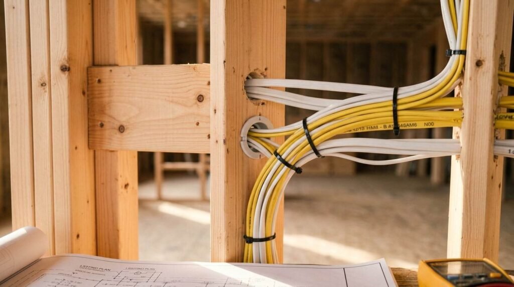
Factory wiring happens on an assembly line with jigs, templates, and repeatable circuit layouts. Crews run cable through open framing at waist height, which produces cleaner routing than most field work.
Site-built wiring runs after framing and sheathing, so electricians work around finished structure. Prefab flips that order, and it pays off in consistency.
The tradeoff is flexibility. Changes cost real money once a module hits the line, so the design has to be right before production starts.
Core Components of a Prefab Electrical System
Every prefab electrical system shares the same backbone: service entrance, meter base, main disconnect, main panel, branch circuits, grounding electrode system, and bonding conductors. Add device boxes, luminaires, and equipment feeders on top of that.
Modules also carry unique elements. Junction boxes at the marriage line, whips for crossover connections, and labeled pigtails all exist so two halves become one system.
I go deeper on each part in the core electrical components guide, since each one deserves its own explanation.
Why Design Happens Before the Home Is Built
Prefab schedules compress construction into weeks instead of months. That speed only works because the electrical plan is finalized upfront and approved before cutting begins.
Homeowners who decide on an EV charger, a heat pump, or a solar array early get those circuits roughed in at almost no extra labor cost. The same additions after delivery mean opening walls.
I push every client to finalize their wish list during design review, not during setting week.
Load Calculation and Service Sizing for Modular Homes
A load calculation adds up the electrical demand of every fixed appliance, heating and cooling unit, and general lighting circuit to determine the service size the home needs. The National Electrical Code sets the method in Article 220, and inspectors expect the math on paper.
Skipping this step is how homes end up with breakers that trip every winter. I have seen 100-amp panels fighting a heat pump, a dryer, and an induction range at the same time.
Estimating Total Household Electrical Load
The standard method assigns 3 volt-amperes per square foot for general lighting, then adds fixed appliance loads, HVAC, and dedicated equipment. Demand factors reduce the total, since not everything runs at once.
A 1,600-square-foot prefab with electric heat, an electric range, and a dryer typically calculates out between 120 and 160 amps. Gas appliances drop that number sharply.
Choosing Between 100-Amp and 200-Amp Service
Older manufactured homes commonly shipped with 100-amp service, and many still run it today. New builds almost always get 200 amps because electrification keeps raising demand.
I recommend 200 amps on nearly every project now. The upgrade cost at build time stays modest, and it removes the ceiling on future additions. A detailed breakdown lives in the electrical panel upgrade guide.
Planning Capacity for Future Additions
Capacity planning means leaving both amperage headroom and physical breaker spaces. A panel with zero open slots forces tandem breakers or a subpanel later.
I ask for a minimum of six spare spaces on every main panel. That covers a future EV charger, a hot tub, a shop feeder, and a solar interconnect without touching the enclosure.
Panel Placement, Subpanels, and Distribution Layout
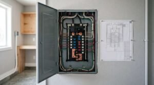
Panel placement decides how efficiently every circuit in the home routes. The main panel wants a spot close to the service entrance, with clear working space, and outside bedrooms, bathrooms, and closets.
Prefab adds one more constraint. The panel has to sit inside a single module, since a panel straddling the marriage line is not buildable.
I usually land it in a utility room, laundry area, or an interior garage wall.
Where the Main Panel Belongs in a Prefab Layout
Code requires 30 inches of width and 36 inches of clear depth in front of the panel. That working space cannot host a water heater, shelving, or a washing machine.
Short service runs also matter. Every extra foot of feeder cable between the meter and the panel adds cost and voltage drop.
When a Subpanel Makes Sense
A subpanel makes sense when circuits cluster far from the main panel, when a second module carries heavy loads, or when a detached garage, shop, or ADU needs its own distribution point.
Long multi-module homes benefit most. One feeder crosses the marriage line, and the subpanel serves the far half.
Detached structures follow their own feeder and grounding rules, which I break down in the detached structure wiring guide.
Circuit Grouping by Room and Function
Good circuit grouping keeps related loads together and spreads heavy draws across both panel legs. I group bedrooms by zone, keep kitchens on their own dedicated small-appliance circuits, and isolate the mechanical room.
Balanced legs reduce nuisance tripping and keep the neutral load low. Labeling matters just as much, and every panel I sign off on gets a typed directory.
Wiring Methods, Conduit, and Module Connection Points
Wiring method means the specific cable or raceway system used to carry conductors through the home. Prefab manufacturers overwhelmingly use nonmetallic sheathed cable inside walls, with conduit reserved for exposed runs, exterior segments, and equipment feeders.
The details change at module boundaries. Every crossover point needs an accessible, code-compliant connection.
Romex, Conduit, and Flexible Wiring Choices
Nonmetallic sheathed cable, commonly called Romex, handles almost all branch circuits. It installs fast, staples cleanly to studs, and passes inspection in dry interior locations.
Conduit takes over where cable needs mechanical protection. Underground feeders, meter-to-panel runs, and exposed basement or crawlspace segments all call for it.
Flexible metal conduit and liquid-tight whips connect HVAC equipment and anything that vibrates.
Marriage Line Splices Between Modules
The marriage line is the seam where two modules join. Circuits that cross it terminate in accessible junction boxes on both sides, with labeled conductors ready for field splicing.
Setting crews connect those splices after the modules are joined and leveled. Every box stays accessible, since buried splices fail inspection every time.
I check marriage line boxes first on any prefab electrical walkthrough.
Protecting Wiring During Transport and Setting
Modules travel on highways, and vibration works staples loose and chafes cable jackets. Manufacturers protect runs with nail plates, extra staples, and foam padding at pinch points.
I inspect for damage before drywall closes at the site. A nicked conductor found on setting day costs minutes to fix and thousands to chase later.

Grounding, Bonding, and Surge Protection
Grounding creates a low-resistance path to earth, and bonding ties all metal parts of the system together so they sit at the same potential. Both exist for one reason: to keep fault current away from people.
Prefab homes complicate this because the structure arrives with its own metal frame and factory bonding. Site work has to integrate with what the factory already built.
Surge protection sits on top as the layer that guards electronics.
Grounding Electrode Systems for Prefab Foundations
A grounding electrode system connects the service to earth through ground rods, a concrete-encased electrode, a metal water pipe, or a combination. Permanent foundations usually allow a concrete-encased electrode, which performs better than rods alone.
Pier-and-beam and crawlspace foundations typically use driven ground rods. Two rods spaced at least six feet apart satisfy code when soil resistance is unknown.
Bonding Metal Frames and Chassis
Manufactured and modular homes ship with a steel chassis or frame that requires bonding to the electrical system. That bond connects through a dedicated conductor to the panel ground bus.
Metal siding, ductwork, gas piping, and water piping all need bonding too. Missing bonds are one of the most common inspection failures I encounter on prefab sites.
Whole-Home Surge Protection
Whole-home surge protection installs at the panel and clamps voltage spikes before they reach circuits. Current code requires surge protective devices on new dwelling unit services.
I install a Type 2 device at the main panel on every project. Point-of-use strips still help at sensitive equipment, and they cost almost nothing to add.
Code Compliance, Permits, and Inspection Milestones
Code compliance for prefab electrical work runs on two tracks. The factory portion follows the standard that governs the home type, and the site portion follows local building and electrical code enforced by the local authority having jurisdiction.
Knowing which track applies to your home changes who inspects what. I sort this out with every client during planning, because the answer drives the permit path.
National Electrical Code Requirements That Apply
The National Electrical Code covers branch circuit sizing, GFCI and AFCI protection, outlet spacing, working clearances, grounding, and surge protection. Modular and panelized homes follow the NEC as adopted by the state or municipality, and adoption cycles vary widely.
Some states run the 2023 edition; others still enforce 2017 or 2020. I always verify the adopted edition before finalizing a design, because AFCI and surge requirements changed significantly between cycles.
HUD Code vs. Modular vs. Panelized Rules
HUD-code manufactured homes follow federal construction standards under the Manufactured Home Construction and Safety Standards, which preempt local building code for the factory-built portion. The electrical system inside the home is inspected under that federal program.
Modular homes follow state building code and the NEC, with third-party factory inspection standing in for local rough-in inspection. Panelized and kit homes are treated as site-built, so local inspectors handle everything.
Site work always falls under local jurisdiction regardless of home type. Service entrance, meter, grounding, and utility connection get inspected locally in all three cases.
Factory Inspection and Final Site Inspection
Factory inspection happens on the production line, with a third-party agency or federal inspection agency verifying wiring before walls close. That inspection produces the label or data plate on the finished home.
Site inspection covers the foundation, service entrance, feeder, grounding electrode, marriage line splices, and final energizing. Most jurisdictions run at least two visits: one before backfill and one at final.
I schedule those inspections during setting week so utility connection does not stall.
Utility Connection and the Site Electrical Plan
The site electrical plan documents how power reaches the home from the utility source, where the meter and disconnect mount, and how feeders route to the structure. Utilities review and approve this plan before setting a meter.
This is the piece homeowners forget until it delays occupancy. Utility scheduling runs on its own timeline, and it rarely bends.
I file the service application the moment the site plan is stamped.
Overhead vs. Underground Service Entrance
Overhead service drops from a utility pole to a mast on the home or a nearby pole. It costs less and installs faster, but it stays visible and vulnerable to storms.
Underground service runs in conduit from a transformer or pedestal to the meter. It costs more because of trenching, and it delivers better reliability and appearance.
Rural prefab sites with long driveways often need an intermediate pole or pedestal, which changes the cost picture substantially.
Meter Base and Disconnect Placement
The meter base mounts on an exterior wall or a nearby pedestal at a height the utility specifies, usually between four and six feet. Utilities require clear, unobstructed access for meter reading and service work.
An exterior disconnect gives firefighters and technicians a single point to kill power. Many jurisdictions now require it as an emergency disconnect on all new dwellings.
Trenching, Feeders, and Detached Structures
Underground feeders need proper burial depth, conduit, warning tape, and correctly sized conductors for the run length. Voltage drop drives conductor size on long runs more than ampacity does.
Detached garages, shops, workshops, and ADUs each get a feeder, a subpanel, and their own grounding electrode. I plan those trenches at the same time as the main service to avoid digging twice.
Landscaping and driveway work should follow trenching, not precede it.
Lighting, Outlets, and Room-by-Room Circuit Planning
Circuit planning assigns every outlet, switch, and fixture to a specific breaker, sized and protected for its load. This is where a home either feels well designed or leaves the owner hunting for an extension cord.
I walk every floor plan room by room and mark where furniture, appliances, and daily habits actually put demand.
Outlet Spacing and Kitchen Circuit Requirements
Code sets the general rule that no point along a wall sits more than six feet from a receptacle. That translates to outlets every 12 feet, plus any wall two feet wide or more.
Kitchens carry stricter rules. Countertops need receptacles within two feet of each end and every four feet along the run, fed by at least two dedicated 20-amp small-appliance circuits.
I add a third kitchen circuit on most builds, since coffee makers, air fryers, and toasters now run simultaneously.
GFCI and AFCI Protection Zones
Ground-fault circuit interrupter protection covers wet and damp locations: bathrooms, kitchens, laundry, garages, basements, crawlspaces, and all exterior receptacles. It trips on current leaking to ground.
Arc-fault circuit interrupter protection covers nearly all living-area branch circuits and trips on the signature of an arcing fault. Newer code editions expanded AFCI coverage significantly.
Combination breakers handle both functions in one device, which simplifies panel layout.
Lighting Layers and Switch Logic
Layered lighting combines ambient, task, and accent sources so rooms work at different times of day. Recessed cans alone leave harsh, flat rooms.
Switch logic matters just as much. Three-way switching at both ends of hallways and stairs, plus switched outlets in bedrooms, prevents dark-room fumbling.
Dimmers on ambient circuits give flexibility for almost no added cost, and I spec LED-compatible models exclusively.

HVAC, Appliance, and High-Draw Equipment Circuits
High-draw equipment needs dedicated circuits sized to the nameplate rating of the specific unit installed. Sharing a circuit between two heavy loads guarantees nuisance trips.
Prefab designs lock these circuits in early, since the wire runs and breaker spaces get built into the module. I collect appliance specs before the plan goes to production.
Dedicated Circuits for Major Appliances
Electric ranges typically need a 40- or 50-amp 240-volt circuit. Electric dryers need 30 amps at 240 volts, water heaters 30 amps, dishwashers and disposals 15 or 20 amps each, and microwaves their own 20-amp circuit.
Refrigerators do best on a dedicated 20-amp circuit. It keeps the compressor cycling off shared kitchen loads.
Full appliance-by-appliance requirements live in the appliance circuit requirements guide.
Mini-Split and Heat Pump Electrical Needs
Ductless mini-splits usually run on a single 15- to 30-amp 240-volt circuit per outdoor unit, with a liquid-tight whip and a local disconnect at the equipment. Multi-zone systems consolidate on one larger circuit.
Central heat pumps need a circuit for the outdoor unit plus a separate circuit for the air handler and any electric backup heat strips. Backup heat drives the biggest load in the whole home on cold mornings.
I coordinate with the HVAC contractor before sizing, since equipment selection changes the numbers.
EV Charger Rough-In
A Level 2 EV charger needs a 240-volt circuit, commonly 40 to 60 amps, landing in a garage or exterior wall location. Roughing in the conduit and breaker space during the build costs a fraction of retrofitting.
I install the circuit even when the client has no electric vehicle yet. Resale value and future flexibility both improve, and the wall box drops in later in under an hour.
Solar, Battery Storage, and Off-Grid Readiness
Solar readiness means designing the electrical system so a photovoltaic array, inverter, and battery bank connect without rework. Prefab roofs and panels make this planning especially valuable, because access gets harder after finishing.
Rooftop solar keeps growing across US housing, with residential solar capacity expanding steadily according to EIA data, and prefab builders increasingly ship solar-ready packages.
Designing for Solar From Day One
Solar-ready design covers roof structural capacity, conduit pathways from roof to inverter location, adequate panel busbar rating, and a reserved interconnection breaker space. Roof penetration points get flashed correctly during manufacturing.
I also reserve wall space near the panel for the inverter and rapid shutdown equipment. Retrofitting that space is the hardest part of a late solar addition.
Complete planning steps appear in the solar-ready home wiring guide.
Battery Backup and Critical Load Panels
A critical load panel, sometimes called an essential loads subpanel, separates the circuits that stay powered during an outage. Refrigeration, well pump, furnace controls, lighting, and a few outlets belong there.
Batteries feed that panel through an inverter and automatic transfer equipment. Sizing the critical load panel correctly keeps battery costs reasonable, since backing up the entire home multiplies capacity needs.
Generator Interlocks and Transfer Switches
A manual transfer switch or panel interlock kit prevents a generator from backfeeding utility lines. Interlock kits cost less and work well for portable generators feeding a main panel.
Standby generators use an automatic transfer switch that senses an outage and starts the unit. Both approaches need a properly sized inlet, conductor run, and generator location that respects clearance and exhaust rules.

Smart Home Wiring and Low-Voltage Infrastructure
Low-voltage infrastructure covers the data, communication, and control cabling that runs alongside line-voltage circuits. Wireless devices work, but hardwired backbones stay faster and more reliable.
Prefab is the ideal time to install it. Open framing on the factory line makes cable pulls trivial compared to fishing walls later.
Structured Cabling and Network Runs
Structured cabling means running Category 6 or 6A cable from a central enclosure to every room that needs data. Wireless access point locations on ceilings deserve their own runs.
A network enclosure needs power, ventilation, and space for a router, switch, and patch panel. I size it one step larger than the current device count.
Coaxial cable still serves some TV and internet setups, so I run it in parallel where the client wants it.
Smart Switches, Sensors, and Control Panels
Smart switches need a neutral conductor in the switch box, which older designs sometimes omit. I confirm neutrals at every switch location during design.
Sensors for water leaks, smoke, temperature, and occupancy either run on batteries or need low-voltage feeds. Hardwired smoke and carbon monoxide alarms interconnect on a dedicated circuit and require a battery backup.
Control panels for security, irrigation, and automation want a defined home near the network enclosure, not scattered across three closets.
How much does electrical work cost for a prefab home, and who handles it?
Electrical Design Cost Factors and Budget Planning
Electrical cost for a prefab home splits into the factory-included portion, already priced into the home, and the site portion quoted separately by a licensed electrician. Homeowners get surprised when they assume the base price covers everything.
I always ask for a written scope split before contracts get signed.
What Drives Electrical Cost in Prefab Projects
Service size, distance from the utility source, trenching length, panel count, and the number of dedicated circuits drive most of the variation. Soil conditions and rock add real money to underground work.
Upgrades multiply quickly. EV chargers, solar interconnects, generators, and whole-home surge protection each add materials, labor, and sometimes a permit revision.
Rural sites cost the most, because the utility run itself often exceeds every other line item.
Factory-Included vs. Site-Added Electrical Scope
Factory scope typically covers interior branch circuits, device boxes, fixtures on the plan, the main panel, and the chassis bond. It stops at the module boundary.
Site scope covers the service entrance, meter base, disconnect, feeder to the panel, grounding electrode system, marriage line splices, exterior devices, and final energizing. Detached structures always fall here.
I write both columns on a single sheet so nothing lands in a gap between two contractors.
Common Electrical Design Mistakes in Prefab Homes
The mistakes repeat across projects. Undersized service tops the list, followed by panels with no spare breaker spaces and outlet layouts that ignore how the family actually lives.
Buried or inaccessible main line junction boxes fail inspection every time. Missing chassis bonds and incomplete grounding electrode systems come a close second.
Late-stage change orders cause the rest. Deciding on a hot tub, a shop, or an EV charger after production locks costs three to five times what early planning costs.
I catch most of these in a single design review meeting. A pre-construction electrical checklist keeps the conversation organized.

Working With Electricians, Manufacturers, and Inspectors
Three parties touch a prefab electrical system, and clear boundaries between them prevent finger-pointing. The manufacturer builds and warrants the factory portion, the electrician handles site work, and the inspector verifies both against code.
I coordinate all three on a single timeline. Setting week runs smoothly only when everyone knows their date.
Who Is Responsible for Which Part of the System
The manufacturer owns everything inside the module envelope and the factory label that certifies it. Warranty claims for factory wiring go to them.
The site electrician owns the service entrance, feeder, grounding, splices, and anything added after delivery. Local permits list that electrician as the responsible party.
The inspector approves, and utility crews energize only after approval clears.
Questions to Ask Before Signing Off on a Plan
I ask five things on every project. What service size is included, how many spare breaker spaces exist, which circuits are dedicated, where the panel sits, and what the site electrical scope excludes.
Two more questions close the gap. Who pulls the permits, and what is the inspection sequence tied to the delivery date?
Written answers beat verbal ones every single time.
Maintaining and Upgrading a Prefab Electrical System
Maintenance for a prefab electrical system looks like any other home, with a few extras tied to the chassis and the marriage line. Torque on panel connections loosens over time, especially after the settling that follows a new set.
I recommend a professional inspection at year one and every five years after. Testing GFCI and AFCI devices monthly takes seconds and catches failed protection.
Upgrades follow capacity. Panel replacement, service increases, subpanel additions, and rewiring aging manufactured homes all sit within reach when the original design left headroom. Older units with aluminum branch wiring need aluminum wiring remediation before any load increase.
Conclusion
Electrical system design for prefab homes ties together load calculations, panel layout, wiring methods, grounding, code compliance, utility connection, and circuit planning into one plan.
Each section here points toward deeper resources on panels, appliance circuits, solar readiness, and inspection sequencing across the broader prefab and electrical service cluster.
We connect you with licensed electricians who design and finish prefab electrical systems correctly. Contact Mr. Local Services to start your plan today.
Frequently Asked Questions
What amp service does a prefab home need?
Most new prefab homes need 200-amp service. Smaller homes with gas appliances sometimes work on 100 amps, but electrification pushes nearly every new build to 200.
Who wires a prefab home, the factory or an electrician?
Both. The factory wires interior circuits and installs the panel, then a licensed site electrician connects the service, grounding, and marriage line splices.
Does prefab electrical work need a permit?
Yes. Site electrical work always requires a local permit and inspection, even when the factory portion carries its own third-party or federal certification label.
Can I add solar to a prefab home later?
Yes. Adding solar later works best when the original design reserved roof pathways, panel busbar capacity, and a breaker space for interconnection.
Where should the electrical panel go in a modular home?
Inside a single module, near the service entrance, with 36 inches of clear space in front. Utility rooms, laundry areas, and garage walls work well.
Are prefab homes wired differently than site-built homes?
The methods match, but the sequence differs. Factory crews wire open framing on an assembly line, then field electricians splice modules together on site.
How much does the site electrical portion cost?
Cost depends on service size, trenching distance, and upgrades. Rural sites with long utility runs cost the most, so get a written site scope early.